NEW RHINO TOOLS!
Variable offset fillet/chamfer Surface from curve network
Record history
Block instances
Extend curve/extend surface
Fillet surface
DESIGN REVIEW
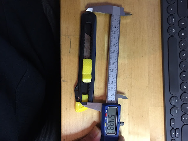
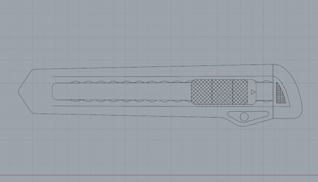
Duplication (measure and model)
Grouping, polygon count, closing model
Reducing poly count/Increasing poly count
File preparation,
Nesting Files in Print area
Show naked edges
Introduction to departmental 3D printing
Outsourcing/Shapeways/
Form 2
Make a ring.
Your CASE by CASE project should be no bigger than
2.75" x 2.75" x 2.75"
Stereolithography (SLA)
145 × 145 × 175 mm
5.7 × 5.7 × 6.9 in
Resolution
25, 50, 100 microns
0.001, 0.002, 0.004 inches
Minimum Supported Wall Thickness
Recommended: 0.4 mm
A supported wall is one that is connected to other walls on two or more sides. A supported wall smaller than 0.4 mm may warp during the peel process.Minimum Unsupported Wall Thickness
Recommended: 0.6 mm
An unsupported wall is one that is connected to other walls on fewer than two sides. An unsupported wall that is smaller than 0.6 mm may warp or detach from the model during printing.
Maximum Unsupported Overhang Length
Recommended: 1.0 mm
An overhang refers to a part of the model that sticks out horizontally parallel to the build platform. Printing such features without supports is discouraged, as the layers cannot maintain their structure. Horizontal overhangs will be slightly deformed beyond 1 mm and become increasingly deformed as the length of the overhang increases. You can turn on “internal supports” in PreForm to ensure your overhangs are supported.
Minimum Unsupported Overhang Angle
Recommended: 19° from level
The overhang angle refers to the angle from horizontal that the overhang sticks out. Printing at an angle less than 19° could cause the overhang to break off the model during the peel process. Rotate your part so flat surfaces can be held up by supports if they are not already self-supporting. See the “Print Flat Surfaces at an Angle” section of our Model Orientation article.
Maximum Horizontal Support Span/Bridge
Recommended: 21 mm
(5 mm width × 3 mm thick)
A span is the distance between two intermediate supports of a structure. While printing horizontal spans is discouraged, certain geometries print well. For a 5 mm wide and 3 mm thick beam, spans longer than 21 mm are likely to fail. Wider beams must be kept shorter to avoid breaking during the peeling process.
A span is the distance between two intermediate supports of a structure. While printing horizontal spans is discouraged, certain geometries print well. For a 5 mm wide and 3 mm thick beam, spans longer than 21 mm are likely to fail. Wider beams must be kept shorter to avoid breaking during the peeling process.
Minimum Vertical-Wire Diameter
Recommended: 0.3 mm (7 mm tall) to 1.5 mm (30 mm tall)
A wire is a feature whose length is greater than two times its width. The ratio is key to printing wires; at 0.3 mm thickness you can print up to 7 mm tall before you start to see waving. 1.5 mm wires can get up to 30 mm tall without defects.
Minimum Embossed Detail
Recommended: 0.1 mm
Embossed details are shallow raised features on your model, such as text. Details smaller than 0.1 mm in thickness and in height may not be visible on your print.
Minimum Engraved Detail
Recommended: 0.4 mm
Engraved details are imprinted or recessed features on your model. Details recessed less than 0.4 mm in thickness and in height may not be visible because they will be fused with the rest of the model during the print process.
Minimum Clearance
Recommended: 0.5 mm
Clearance is the amount of distance needed between two moving parts of a model (e.g., the distance between gears or joints). A clearance of less than 0.5 mm may cause parts to fuse.
Minimum Hole Diameter
Recommended: 0.5 mm
Holes with a diameter less than 0.5 mm in the x, y, and z axes may close off during printing.
Minimum Drain Hole Diameter
Recommended: 3.5 mm diameter
Drain holes are recommended for resin to escape in models that are a fully enclosed cavity (like a hollow sphere or hollow cylinder printed directly on the build platform). Without drain holes of at least 3.5 mm in diameter, the part may trap resin and lead to an explosion of the print.


